STC News
Milestones/History

Support Beam
STC100 & STC100W
STC150
STC200
SOAR300
SOAR500
ET Micro Grid

Description
Testimonials
Videos
Animations
Funding
Actions & Partners

Sky Train Corporation - Technical Specifications

New (VAST) System Math:
" Vertically Articulated Suspended Technology"


BS = Bottom-supported System
HS = High speed
SS = Suspended System

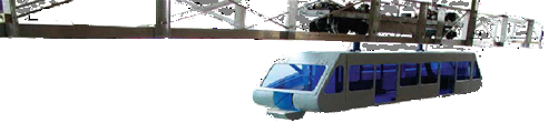
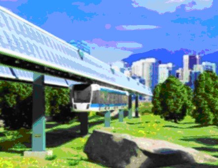
Sky Train discloses the secret behind their system; the World's most practical and fastest train!

Higher Speed Rail:
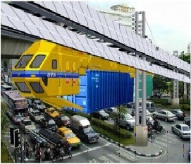
Our company conducted in October 2015 another port automation study. Through this study we have discovered that the implementation of our innovative STC150 logistic system, to transport containers from sea ports to dry ports (inland intermodal terminal), and vice versa, could replace the traditional logistic systems.

This would create a revenue source which, in turn, could simplify Public Transportation funding using our STC100W). In this practical Dual System; both the STC150 and the STC100W use the same elevated structure. Only good scheduling is needed!

Why choose Sky Train?

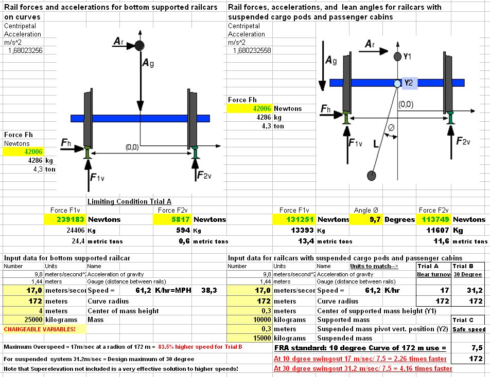
Normal bottom supported trains have to keep low speeds in curves to avoid derailment because of the centrifugal force. With suspended trains this risk is inherently reduced, and with STC's "VAST" design even more so.

As seen in the little grey table above right, the limiting speed for a curve with 70 meter radius is 27 km/hour (or 7.5 meter/sec. according to FRA standards). At this speed the load distribution of a 25 ton vehicle is 14.8 metric tons on the curve's outer rail and 10.2 metric tons on the inner rail. Note that 14.8/10.2 gives a ratio of 1.45.

But with STC's suspended "VAST" design, the distribution is 13.4 metric tons on the outer and 11.6 tons on the inner rail. This is a much more even distribution, and it allows for much safer operation.

Take an example with higher speed; at 67 km/hour the load distribution is 14.5 tons outer and 10.5 tons on the inner rail, using STC's "VAST" technology.
At this increased speed the vertically linked load swings out because of centrifugal force; adding to passengers' comfort by swinging 9.7 degrees from center.
In addition, the "VAST" design would now travel 2.25 times faster, while greatly reducing track and switch damage and wear.

STC's original system design focused on a maximum swing of 10 degrees resulting from our 2002 testing with the Florida Largo Railroad Group. With this Modelling Application (AP) we can appreciate the precise effects that would result, by variating the various parameters as a guide for bottom supported (BS) and suspended (SP) systems. The proof is that vertical forces always total the vehicle weight!

Our first goal was that during structure design, (critical system cost), we could exactly predict the forces on the structure itself, especially on curves. This has been now greatly streamlined, allowing the designers to calculate force on the various components, thus increasing safety.

The second goal was to easily demonstrate, by changing the many variables, the speed difference between the Suspended Mode (SP) and conventional Rail (BS) or Truck.

This very same principle can be applied also to road vehicles; Tank cars, trash and sand carriers or trailers to determine rollover.

This AP allows for modelling vehicle weights, and in the future for us to build the most practical Maglev Vehicle, which will have a 30 degree swing design, for passenger vehicles - shown in Trial C - , and allowing for higher speed on curves (more than 4 times as fast).

At the present, we still use the Trial A (10 degree swing) design, which allows for speeds up to 2.25 as fast.


Below is a comparison between supported and suspended systems as regards rail forces and accelerations.
It can be downloaded as a PDF file.


It is suggested that you keep two copies in order to remember settings, print out a hard copy if you need to.
If you want to discuss anything you can call Karl Guenther at 727-939-2177, you might also be forewarded to the main author, Tad Winiecki.
For background details about FRP 10 degree curve, see these calculations, used in survaying locations.

Dear Viewer:
To explain the above chart we have changed the values for you to save time. We have changed one value, the speed of entering a curve to the left, which has a 172 meter Radius. These calculations show the results on a bottom supported system like the one on the LEFT above, and a suspended system like the Sky Train on the RIGHT. We use the suggested tests on the bottom Right side of the above chart marked "A", "B", and "C".

First, we suggest reviewing the results below!
As a guide to a responsible review; when you see a color picture of two steel rail wheel drawings; the left side is the typical vehicle with wheels underneath and the right set of wheels are above, allowing the load to swing on curves.

Some things to notice:

1) Operating conditions are changeable in the green boxes, look at the ones on the left hand side for bottom supported (BS) and center for suspended (SP) as the two equal weight vehicles of 25,000 kilograms are evaluated

  a. Pictured above you see a value of Trial A speed at 17 meters/second = 61.2 Kilometers/hour = 38.3 Miles/hour and also on the second suspended system

  b. The second value is the radius of the curve In meters for both at 172 m

2) These two determine the Forces on the rail or road if rubber tires, framed in green
  A. The horizontal (side force Fh is the same) on both vehicles shown as 4.3 metric tons, resulting in BS Swing angle of 9.7 degrees

  B. From left to right BS F1v = 24.4 metric tons (Mt) and on SP F1v = 13.4 Mt

  C. Then on the other side BS F2v = 0.6 metric tons compared to SP F2v = 11.6 Mt

  D. The BS vehicle is exceeding the safe speed specified in Trial C in the bottom RH framed box with a weight distribution between the rails of 24.4 to .6 or 42.3 to 1 and SP distribution of 1.16 to 1

  E. Ratios for safe BS curve speed Trial C speed at 7.5 meters/second = 27.0 Kilometers/hour = 16.9 Miles/hour also on the suspended system The second value is the radius of the curve In meters for both at 172 m. swing of only 1.9 degrees

  F. The horizontal (side force Fh is the same) on both vehicles shown as 0.8 tons

  G. From left to right BS F1v = metric tons = 14.8 T and on BS F2v = 10.2 Mt

  H. Then on the other SP F1v = 12.7 metric tons compared to SP F2v = 12.3 Mt

  I. Equaling BS weight distribution between the rails of 1.45 to 1 and an SP distribution of 1.03 to 1

  J. Ratios for Maximum design speed of a 30 degree swing Trial B speed at 31.2 meters/second = 112.32 Kilometers/hour = 70.2 Miles/hour also on the horizontal (side force Fh being the same) on both vehicles is at 14.4 tons

  K. From left to right BS F1v = metric tons = 52.6 T and on BS F2v = -27.6 Mt

  L. The BS weight distribution exceeds logic and SP distribution of 1.03 to 1

  M. The equations are no longer valid if F1v exceeds the weight of the vehicle or if F2v is negative and the car will overturn unless there are additional rails and wheels to prevent overturning as on some roller coasters. The suspended vehicle weight on the structure is almost equal on both rails at a 30 degree swingout.

3) Conclusions: While tests and calculations showed in our 2002 Tilt test with the Largo Railroad Largo Central Rail Road Tilt Test that we should attain up 3 times the speed of bottom supported rail (these calculations also holds true for rubber tired vehicles, no wonder the rollovers). We needed this suspension so that we can carry heavy containers without shifting loads. Confirmation and proof of calculations is obvious as you change numbers in the Calculation Table the total weight on each side equals the overall weight of the vehicle assemblies of 25 metric tons

4) STC's associates now feel comfortable after producing our designed vehicles, modifications of what is, into suspended mode with many patents, and that in the near future we and manufacturing partners will produce first the most efficient then add the maglev components moving freight for profit and passengers when needed.

See the PDF file.

Sky Train Corporation Webmaster: Ove Johnsson - Johnson Consulting Last Updated: 2017-06-05